 Advanced Manufacturing


What is a Flip-Flop Circuit?
A flip-flop is a circuit that can hold a state after a short pulse sets it.
While that might not make sense for some, the video will hopefully explain it.
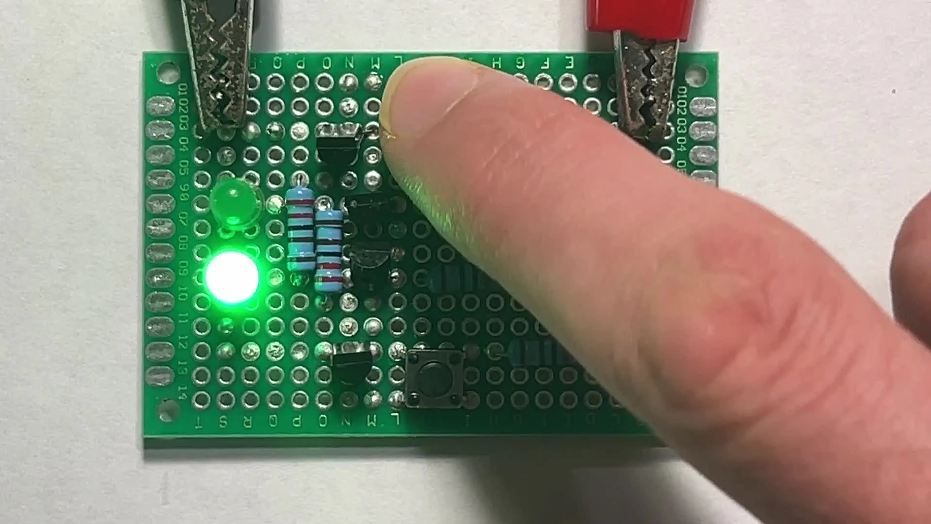
Looking at just one of the LEDs, let’s say the top one, notice how it can be turned on indefinitely with a short click of a button. This is called “setting” the flip-flop.
If we want to turn the top one off, we can click the other button. This is called “resetting” the flip-flop.
Why 2 LEDS?
The reason for two LEDs is to represent the two outputs of the flip-flop, which are often represented with Q and Q (Q not). Q will always be the opposite of Q.

Development
Testing / Prototyping
Using a breadboard, I tested different logic gate designs to see what worked and didn’t work. Then I tested my first complete prototype on a breadboard.

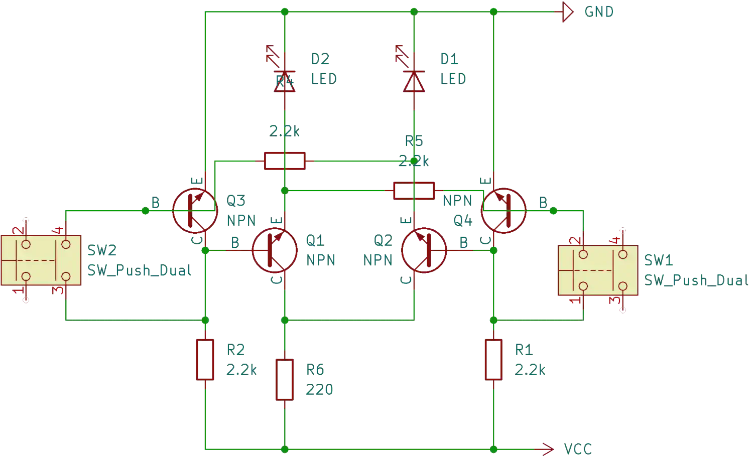
Drawing the circuit
From my breadboard prototype, I drew a schematic using KiCAD.
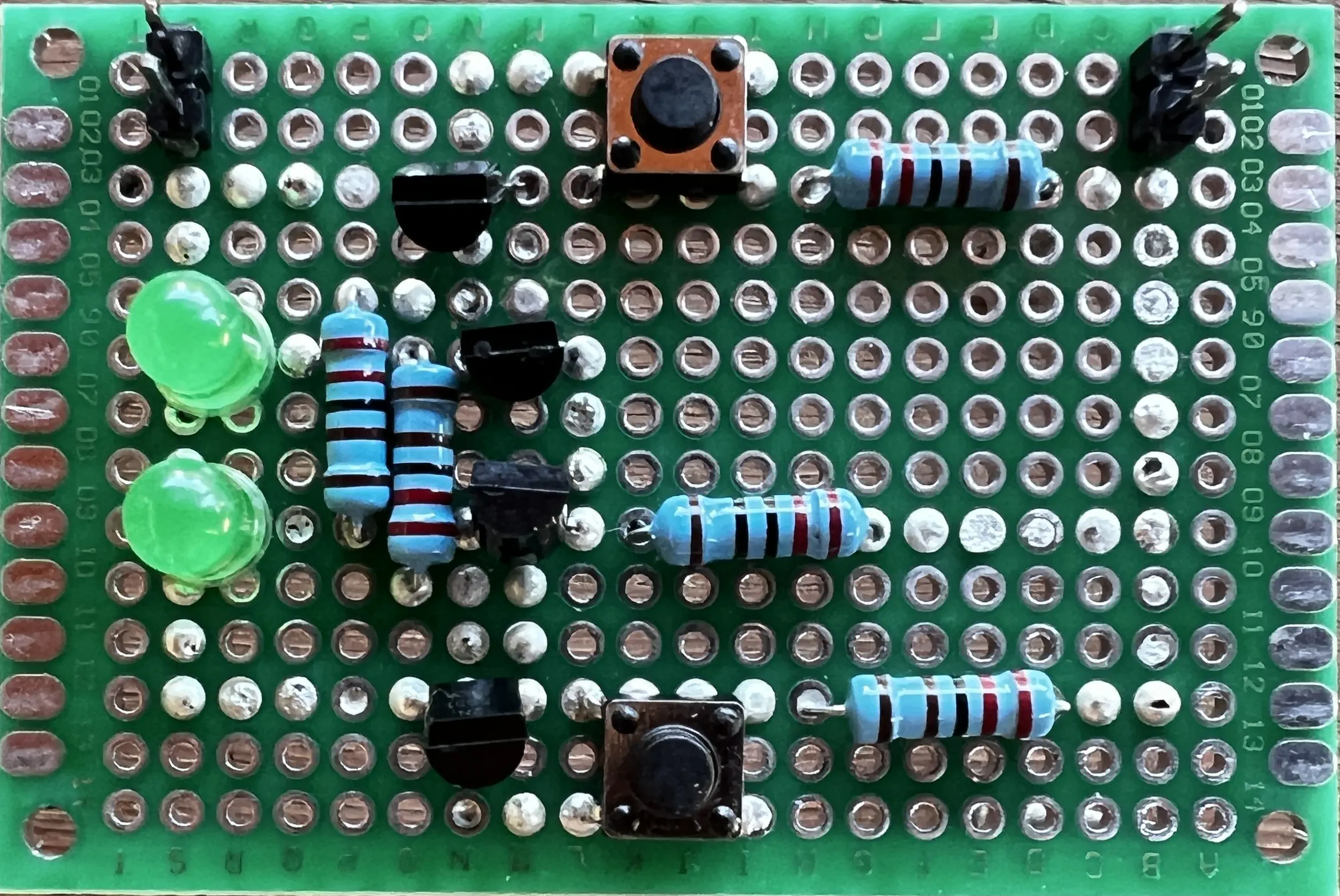
From the schematic, I added lines to a picture of the components placed on an unsoldered breadboard to plan out my solder paths beforehand.
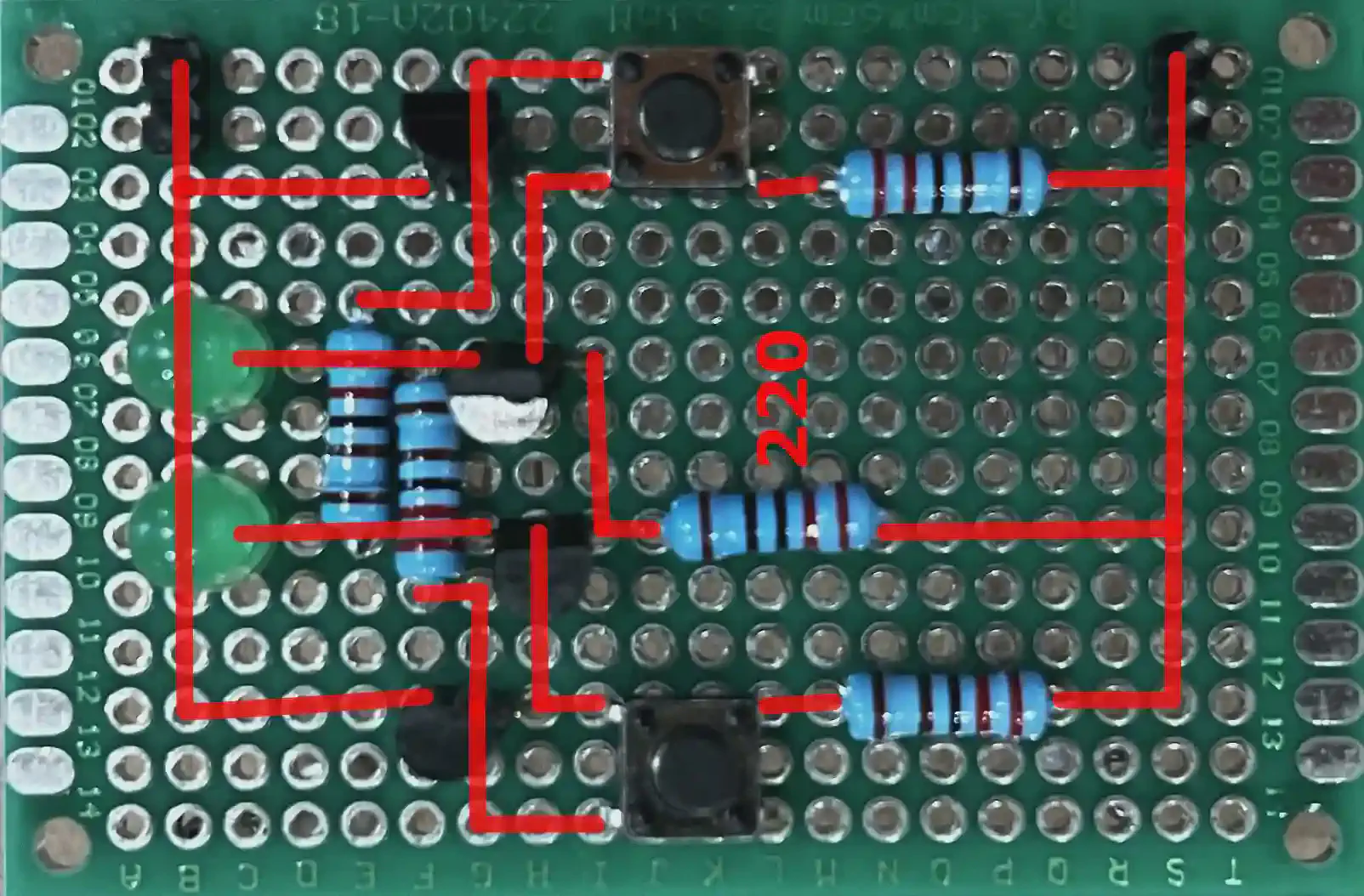
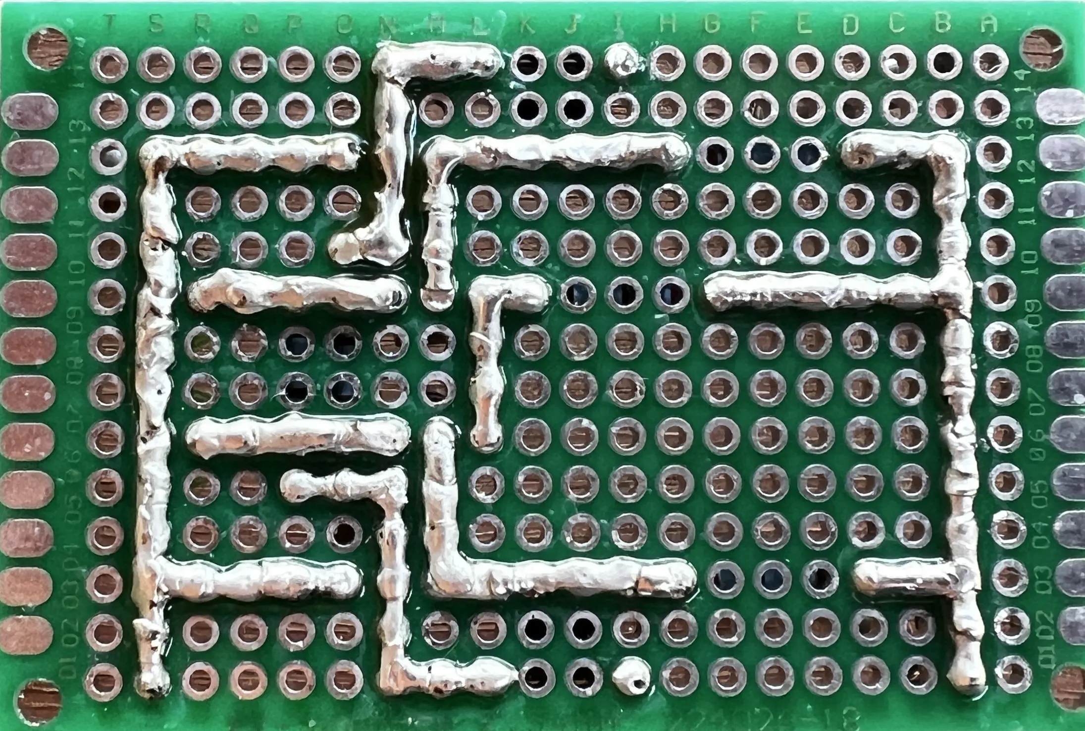
Soldering
As you can see, the traces I soldered on the bottom are a mirror image of the diagram I used above.
Result